
Maximum Bending Radius For Rigid Flex Circuit Boards
Bending Radius For Rigid Flex Circuit Boards
When designing a rigid flex circuit board, you must keep in mind the maximum bending radius, which is determined by various factors. A smaller bending radius limits the amount of stress that can be placed on copper and through holes, which helps reduce the likelihood of damage to the circuit board. The thickness of the substrate, the number of layers and other factors all affect the bending radius limit, so it’s important to consult with manufacturers and use advanced simulation tools to ensure that the bending radius is appropriate for your specific application.
The type of material used for the rigid flex circuit boards also plays a role in determining the bend radius. For example, thicker substrates typically have larger bending radii than thinner ones, as they are less flexible and require a higher bending force to bend properly. In addition, the type of copper used on the rigid flex circuit board can affect the bending radius limit. For example, high-temperature copper requires a larger bending radius than standard copper.
To maximize the durability of a rigid flex circuit board, it’s essential to follow best practices and design guidelines during the PCB fabrication process. This includes using a high-quality material that is resistant to chemicals and solvents. It’s also important to minimize sharp corners on traces, as they can rip or tear during bending. You can minimize the risk of this by using your PCB editor’s filet tool to round off any potentially susceptible corners.
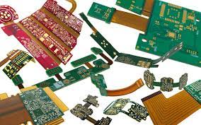
Maximum Bending Radius For Rigid Flex Circuit Boards
During the manufacturing process, it’s also crucial to pay attention to how the copper is plated on the flex circuit board. Plated through-holes (PTH) must be a minimum of 1mm away from adjacent flexible areas to prevent them from getting peeled off during the chemical processing step. To further protect the plated holes, it’s a good idea to add tabs or anchors to these locations.
The bending radius limit for rigid flex circuit boards is usually around 10:1 for static applications and 100:1 for dynamic usage. During dynamic applications, the PCB will be subjected to constant and repetitive bending. The creased flex circuit must be carefully un-creased, and PSA is usually added adjacent to the bending area to adhere the flex circuit to the rigid part of the PCB.
Rigid-flex circuit boards represent a remarkable innovation in electronic engineering, seamlessly blending the benefits of both rigid and flexible PCB (Printed Circuit Board) technologies into a single platform. These specialized circuit boards offer unique advantages, making them increasingly prevalent in various industries ranging from aerospace and medical devices to consumer electronics. In this exploration, we delve into the intricacies of rigid-flex circuit boards, examining their construction, applications, advantages, and future prospects.
The bending radius for rigid flex circuit boards is determined by several factors, including the thickness and number of layers. It’s also important to consider external factors, such as the operating environment and if the flex circuit will be exposed to temperature extremes. By working closely with a manufacturer who has extensive experience in the field, you can be sure that your flex circuit board will have an optimal bend radius and be resistant to damage and other mechanical problems.